Laser Etch Monitoring
| ||||||||||||||||||||||
Overview
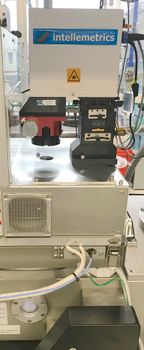
A number of our dry etching systems have Laser Etch monitors installed, for "endpoint detection". These systems allow you to end your etch at a known etch depth, or within a certain layer (with some caveats). This nearly eliminates the need to calibrate etch rates or to use timed etching only, which is especially important in our lab where etch rates can vary depending on the previous etches performed in the chamber.
Laser Etch monitoring works similarly to optical thin-film measurement via reflectivity spectra (eg. like our Filmetrics systems). However, instead of varying the optical wavelength and measuring a fixed thin-film, we measure a constant wavelength and a thin-film that is varying as it is etched. Thus, similar to the thin-film measurements, you can only measure a useful signal when the optical properties (reflection or interference) change during your etch.
For example, Etching from high-reflectivity Aluminum to Lower reflectivity Silicon will usually give you a clear drop showing that your Aluminum has been fully etched-through.
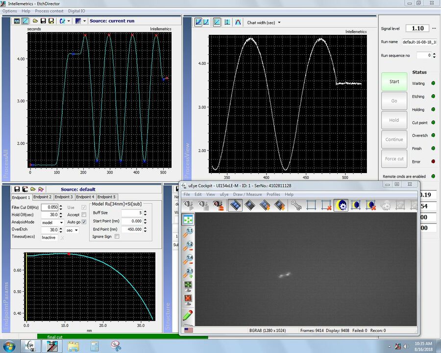
Etching films that are transparent at the laser monitor wavelength (670nm) produces a sinusoidal signal due to optical wave interference which gives you numerous possible stopping points to end the etch upon.
Procedures
General Procedure
The basic method for performing an etch with laser monitoring endpoint, is as follows:
- Simulate or estimate what the laser monitor trace will look like, decide when to stop the etch according to the laser monitor plot.
- Mount the sample such that the laser will be able to reach a region to monitor the etch - typically ~100-300µm wide area.
- Load sample into chamber - wafer transfer only, no etch.
- Align Laser onto area to monitor using co-axial microscope.
- Start laser power monitoring/logging.
- Start Etch (time set longer than expected etch time) - etch only, no wafer transfers.
- Closely observe laser monitor plot, comparing to known/simulated plot.
- Use "Next Step" or "End Step" when appropriate laser monitor trace is reached. Wait for process to complete any final steps.
- Transfer wafer out of chamber.
- Save laser monitor data, turn off laser & microscope illumination.
Specific Procedures
Procedures for specific machines are found on the following pages:
- Intellemetrics Laser Etch Monitor Procedure for Panasonic ICP Etchers
- Installed on Panasonic ICP #1 & ICP #2
- Intellemetrics Laser Etch Monitor Procedure for Plasma-Therm Etchers
- Installed on Plasma-Therm DSE-iii and Fluorine ICP Etcher
- Horiba Laser Etch Monitor Procedure for Unaxis VLR
- Custom Laser Etch Monitor Procedure for RIE#2
- Laser Etch Monitor Procedure for RIE5
Examples
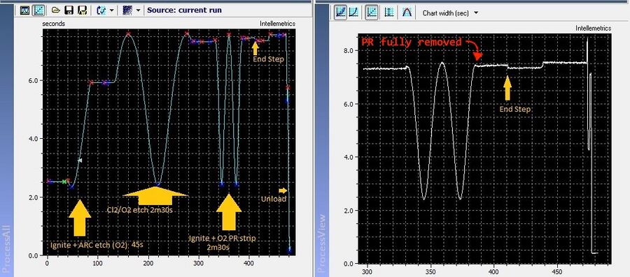
Monitoring Photoresist Etch Rate
Even if you don't use the laser monitor to see when your etched material is removed, monitoring just the photoresist mask is itself very helpful. For example, you can tell exactly when the photoresist is fully etched through during an etch (even if by accident), allowing you to stop the etch at that time, and still determine selectivity if desired.
References
See the following pages for more information about laser endpoint detection.
- Intellemetrics LEP
- The Intellemetrics Manuals are available on the tool computers in the lab - you can copy these to your Nanofiles Sync folder to access them remotely.
- Simulation of Laser Endpoint Signal in Python


