Difference between revisions of "Holographic Lith/PL Setup (Custom)"
(Created page with "{{tool|{{PAGENAME}} |picture=Holograph.jpg |type = Lithography |super= Ning Cao |phone=(805) 839-5689 |location=Bay 6 |email=Ningcao@ece.ucsb.edu |description = Custom Built Int…") |
(cusotme system, updated supervisor) |
||
| (7 intermediate revisions by 2 users not shown) | |||
| Line 2: | Line 2: | ||
|picture=Holograph.jpg |
|picture=Holograph.jpg |
||
|type = Lithography |
|type = Lithography |
||
| − | |super= |
+ | |super= Demis D. John |
| − | |phone=(805) 839-5689 |
||
|location=Bay 6 |
|location=Bay 6 |
||
| + | |description = Custom Interference Lithography |
||
| − | |email=Ningcao@ece.ucsb.edu |
||
| − | | |
+ | |manufacturer = Custom-Built Free-Space Optics |
| + | |toolid=35 |
||
| − | |manufacturer = Kimmon |
||
}} |
}} |
||
| − | = |
+ | ==About== |
| − | The interference lithography system at UCSB uses a 15mW, single-mode, 325 nm HeCd laser that is filtered and expanded by pinhole filters to produce the large area exposure beam. The system uses a simple mirror configuration with a fixed 90 degree angle between the mirror and sample. The entire mirror/sample assembly is rotated in 0.1 degree increments to change the grating pitch from ~ 200 nm to ~ 280 nm (35 to 55 degrees) over an ~ 2 cm x 2 cm exposure area. |
+ | The interference lithography system (aka. Holography) at UCSB uses a 15mW, single-mode, 325 nm HeCd laser that is filtered and expanded by pinhole filters to produce the large area exposure beam. The system uses a simple mirror configuration with a fixed 90 degree angle between the mirror and sample. The entire mirror/sample assembly is rotated in 0.1 degree increments to change the grating pitch from ~ 200 nm to ~ 280 nm (35 to 55 degrees) over an ~ 2 cm x 2 cm exposure area. |
| + | [https://wiki.nanofab.ucsb.edu/w/images/3/33/XHRiC-Anti-Reflective-Coating.pdf XHRiC] bottom anti-reflection coating (BARC) & [[Lithography Recipes#Chemicals Stocked .2B Datasheets|THMR-3600HP]] imaging resist spin-coated to ~80 nm thickness is used for grating exposure. 2-D gratings can be formed by rotating the sample and doing multiple exposures. Total exposure times are controlled by a manual shutter and are generally several minutes in length. |
||
| ⚫ | |||
| + | |||
| ⚫ | |||
| + | A photoluminescence measurement setup is co-located on the optical table. Please see the page for the PL system for more info: |
||
| ⚫ | |||
| + | |||
| ⚫ | |||
| + | *[[Photoluminescence PL Setup (Custom)]] |
||
| ⚫ | |||
| + | |||
| ⚫ | |||
| + | |||
| ⚫ | |||
| + | *Max sample size: ~1.5 inch square uniform exposure area |
||
| ⚫ | |||
| ⚫ | |||
| ⚫ | |||
| + | *Manual optics alignment. |
||
| + | *1-D and 2-D gratings possible, see recipes below. |
||
| + | |||
| + | ==Recipes== |
||
| + | |||
| + | *[[Lithography Recipes#Holography%20Recipes|Lithography Recipes > Holography Recipes]] - developed recipes for 1D (line/space) and 2D (pillars) gratings. |
||
Latest revision as of 20:48, 26 September 2023
|
About
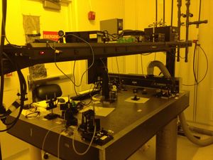
The interference lithography system (aka. Holography) at UCSB uses a 15mW, single-mode, 325 nm HeCd laser that is filtered and expanded by pinhole filters to produce the large area exposure beam. The system uses a simple mirror configuration with a fixed 90 degree angle between the mirror and sample. The entire mirror/sample assembly is rotated in 0.1 degree increments to change the grating pitch from ~ 200 nm to ~ 280 nm (35 to 55 degrees) over an ~ 2 cm x 2 cm exposure area.
XHRiC bottom anti-reflection coating (BARC) & THMR-3600HP imaging resist spin-coated to ~80 nm thickness is used for grating exposure. 2-D gratings can be formed by rotating the sample and doing multiple exposures. Total exposure times are controlled by a manual shutter and are generally several minutes in length.
A photoluminescence measurement setup is co-located on the optical table. Please see the page for the PL system for more info:
Detailed Specifications
- 15 mW single TEM mode HeCd laser (Kimmon)
- Max sample size: ~1.5 inch square uniform exposure area
- ~2 cm x 2 cm uniform exposure area
- Several-minute exposure times (manual shutter)
- Grating period adjustable from ~200 to ~280 nm with rotation stage
- Manual optics alignment.
- 1-D and 2-D gratings possible, see recipes below.
Recipes
- Lithography Recipes > Holography Recipes - developed recipes for 1D (line/space) and 2D (pillars) gratings.
