Difference between revisions of "Goniometer (Rame-Hart A-100) - Operating Procedure"
Jump to navigation
Jump to search
(initial page, mostly copied from "NRL Contact Angle Goniometer - Owners Manual.pdf") |
(image sizing) |
||
| Line 1: | Line 1: | ||
== System Illustration == |
== System Illustration == |
||
| − | [[File:Goniometer (Rame-Hart A-100) - Annotated Photo.png|alt=labeled photo of the contact angle goniometer|none|thumb| |
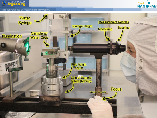
+ | [[File:Goniometer (Rame-Hart A-100) - Annotated Photo.png|alt=labeled photo of the contact angle goniometer|none|thumb|550x550px|The Ramé-Hart A-100 Contact Angle Goniometer and relevant adjustment knobs.]] |
== Measurement Procedure == |
== Measurement Procedure == |
||
Revision as of 09:21, 27 July 2020
System Illustration
Measurement Procedure
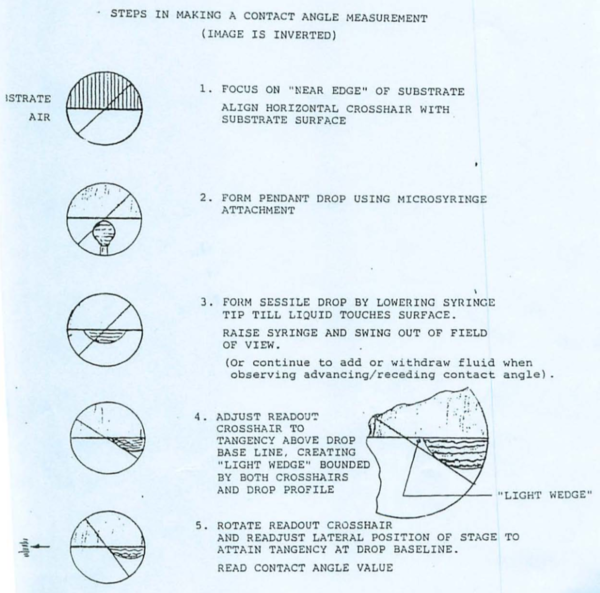
To measure the contact angle of water on a surface, perform the following procedure.
- Note that the image through the scope is inverted upside-down.
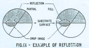
- You will also see a reflection of the water droplet on your polished substrates, as illustrated here:


