ASML Stepper 3 Error Recovery, Troubleshooting and Calibration
Software (PAS) Login/password: ASM / litho (If you accidentally exit Main Menu)
Important Warnings
Pay attention to the Warnings window, and look for these important messages BEFORE you start your exposure. Note that the “warnings” window Can get hidden behind the main PAS software window - click the window's title bar to bring the Warnings window to the front.
- CT Not Initialized
- NOTIFY STAFF IMMEDIATELY, as this means the temperature controller is not maintaining the lens temp. and focus will drift. This can take hours or a day to re-stabilize. The faster we can get this re-enabled, the shorter the time for the lens temperature to stabilize.
- Laser gas refill needed soon or Laser Gas Injection Required or Illumination Maintenance: New Fill Needed:
- BEFORE your exposure, please run the "Laser Refill" procedure below, or you risk the system aborting during your exposure!
- Incoming Air Temp. Out of Range - notify staff if this appears! System focus may drift due to a temperature change in the Bay.
- <<Log Window Full>> (in LOG window) - Please follow the "Error Log Full" procedure below to re-open a fresh log window.
The following messages in the Warnings window do not require any action
- Machine is Idle: Light Source Switched Off - no action needed.
- Empty Input Carrier - in a high-volume foundry this would be an "Operator Error", but not in the NanoFab.
Error Logs: Finding the root-cause of a failure
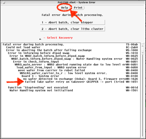
When you get an error, please click the [HELP] button on the error window before choosing an option - usually this shows a simplified Error Chain, which helps us identify root-cause (and thus solution) of the error. You can send a photo of this in your communication to tool owners to help us expedite the fix.
If you can't get the info from this screen (for example if you closed it already or it didn't show useful info), you can find the root-cause in the Error Log window.
To do so, you need to scroll back in the log file until you find the First error that occurred, which will show text similar to the following:
<<timestamp>>
ERROR: WH-XYZYXZ
After this First error, ensuing errors will show that they are linked with text like:
ERROR: WH-123123 (linked to WH-XYZXYZ)
These linked-errors may contain useful information, but most are just passing the error through the system and may not help identify the root problem.
You can typically ignore "WARNING" messages.
Wafer Recovery
See the Wafer Recovery page for procedure on how to recover from an error and get your wafers back.
Error Log full
Log windows shows <<Log File is Full>> and no further messages are appended.
- Close logging window that says "log file full" by Right-Clicking on the Logging title-bar and choose "Quit"
- Right-Click on Blue Desktop, and in the resulting menu:
- Click "Local". A new Logging window should open in the proper location.
Wafer Handler Issues during Batch operation
If the Warnings Window shows "Wafer Handling not initialized', or the Cassettes are not mapping (cassette may be partly lowered), or you opened the Port cover while robots were moving, you need to reset the Wafer Handler.
See the Wafer Handling Reset page for full procedure.
IQC (Image Quality Control) Calibration Check
Use this procedure to check the system's focus calibration. Important before running <300nm feature litho jobs, including focus-exposure matrices (FEM's). It is common to add IQC verification as a step in your traveler before sub-250nm lithography steps.
- Main Menu > Test Manager > Run Tests > Metrology Verification > Image Quality Control
- Accept (Upper Button)
- Perform Measurement
- Choose System Correction
- # Cycles = 1
- # Measurements = 3
- # Corrections = 1
- M "Measure" mode only (does Not update internal lookup tables)
- (UCSB numbers for test 1 3 1 M)
- Accept to run the test
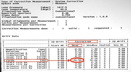
- If [Focus | Mean Correction] < 50nm, system OK, note number in log book
- If [Focus | Mean Correction] > 50nm, run test again, if number keeps dropping, keep running until number is stable
- If [Focus | Mean Correction] is still > 50nm, discuss with engineer. If >>200nm (eg. ±1000nm) contact engineer immediately, this could indicate temperature is not controlled.
- Record the [Focus | Mean Correction] values for each run in the logbook please! This helps us determine whether there is a problem and how to remedy.
- If IQC Focus is out of spec but still within ±250nm, larger features (≥1µm) will typically resolve fine.
Exposing with corrected Focus Offset from IQC
Small features can still be exposed when IQC is >50nm as so:
- Run IQC THREE times, record all 3 focus values in logbook.
- Calculate the average of the 3 IQC Focus values.
- When running your job in “Append Batch”, ADD this averaged Focus Offset value to your exposure's Focus Offset. Dose stays the same.
- For example, if you typically expose at Focus = -0.10 µm (note the units of micrometers), and IQC showed system focus was at +200 nm (nanometers), then you would expose with a Focus Offset of -0.100µm + 0.200µm = +0.100µm
Laser Refill (or laser calling for gas injection)
- Main Menu > Test Manager
- Open Cmd Handler (Cmd Hdl) (Top Menu)
- Illumination and Projection > Illumination
- Use Laser Start if laser asking for gas injection, otherwise do New Laser Fill
Failed Alignment Marks - Choosing new alignment marks for Pre-Alignment
If your job aborted with "Alignment failure" on the E- or P-Chuck, because your alignment marks are damaged, this is how to edit your job to use different alignment marks.
- Edit your job with Modify Job
- Go to Layer Layout > Process Data
- Use Layer: (Prev) / (Next) to select the layer you need to change alignment marks for
- Under Prealignment Mode: Selection: Mark 1___ & Mark 2___ choose the alignment marks to align to, and use a microscope to make sure these alignment marks are (a) present on your wafer and (b) look ok with no defects.
- The wafer schematic shows which alignment marks you are choosing.
- The alignment marks, defined on a previous layer (usually combined with the first litho), are programmed/named in: <to be added: where in the program the AlMks are defined>
- Your "Fine" alignment marks will probably also fail if they're set to use the same marks! Fix this by editing your Wafer Layout > Alignment Strategy, and reduce the number of "required" marks, so some will be allowed to fail. Make sure your Layer Layout > Strategy Selection is using this new/updated strategy.
Abs. Wafer Expansion Too Large, 8/88µm Error Suspected
According to the alignment mark locations the system measured on your wafer, the system has calculated that your wafer has physically expanded by >20ppm (0.000020). This is possible due to stressy films, especially if backside stress compensated. Or you are matching to another 'fab, and their scaling is different than ours.
To increase the allowed wafer expansion to 200ppm, change the following setting in your job:
- Job Definition (select your job) > Wafer Layout > Alignment > Alignment Strategy > Alignment Data
- Set “8/88um check” to Disabled (D)
Or you can change this only on the current wafers (not in the whole job) as follows:
- Task Streaming > Batch Append > Alignment Corrections
- Set “8/88um check” to Disabled (D)

